Table of Contents
VehiCAL Muxer
Description
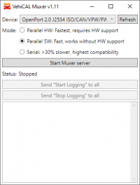
The Muxer allows to start multiple Logger instances and connect them at the same time to the vehicle. It can be used with any protocol. PRO clients are also supported.
Usage
- Start the Muxer.
- Select your J2534 device in the Muxer.
- Press
Start Muxer serverto start the Muxer - In the Logger select the
VehiCAL Muxerinterface. - For connecting to multiple ECU's just start one Logger for each ECU - with the Muxer they can connect at the same time.
Tips
- By default the Muxer has fair scheduling and aims for minimal jitter - you should get the same data rate for both ECU's, limited by the slowest ECU, but the rate of the slowest ECU will be affected very little. If you want to change this, then use the speed limiter in the slowest logger instance to limit the rate a little more. This will bias the scheduler more towards the faster ECU and the total throughput will be higher, at the cost of some jitter.
- The Start/Stop logging buttons can be used to send a “Start Logging” or “Stop Logging” command to all currently connected clients. Note, that the clients have to be actively measuring, not just initialized, because the requests are sent as a backfeed over the active connection.
- Disconnects and/or timeouts when using Muxer can be caused by two factors. The J2534 device having issues with high bus load, or the gateway of the vehicle having issues with high bus load. Solutions:
- If the speed in the loggers is not limited or below the default limit, then limit the speed additionally 10-15% below what you are getting. This is often enough to fix any possible stability issues.
- If you still have issues, use Serial Mode, at the cost of losing up to half of the speed. This however does not significantly increase the bus load, and should always be as stable as logging a single ECU.
Modes
Parallel HW Mode
Parallel HW mode communicates with all control units simultaneously and is the fastest when communicating with multiple control units. It requires a J2534 device that can handle sending and receiving messages with multiple FlowControl filters at the same time. The ISO15765-2 layer is fully performed by the J2534 device.
You can check which devices support parallel mode in the Tested devices list.
Parallel SW Mode
Also communicates with all control units simultaneously, but ISO-TP is done fully in software. It works around the issue of some devices (such as the Tactrix OpenPort) not supporting more than one ISO15765-2 context at a time, however the tradeoff can be reduced maximum speed with some controllers depending on the J2534 device and the ISO15765-2 implementation in the target controller.
The device must have decent drivers that can handle a high bus load. If you have timeout issues with this mode and are unable to solve them by slight speed limiting, then use the Serial Mode.
A special benefit of this mode is that raw CAN connections and ISO15765-2 connections can be mixed, which is not possible in the HW Parallel mode.
Serial Mode
Serial mode is a workaround for devices, that are unable to communicate with multiple nodes at the same time. The serial mode performs round robin servicing of requests, blocking the connection for the entire duration of sending a request and receiving a response.
It is compatible with almost all devices, but at the downside of a 20-30% speed penalty due to not being able to transmit and receive from multiple nodes simultaneously.

